140 GHz Radar Level Transmitter
Industry served
- Power Plant
- Coal & Ore Mines
- Steel Plant
- Paper & Pulp
- Petrochemicals
- Fertilizers Plant
- Pharmaceutical
- Chemical Plant
- Cement Plant
- Water & Wastewater
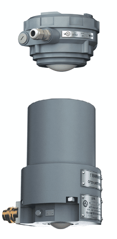
ULM series level transmitters are built on the operating principle of a chirp radar; this principle is better known as FMCW (frequency-modulated continuous wave) (hereinafter, we are using this abbreviation).
The continuous principle (FMCW) is the most optimal for high-precision and weak-reflection level measurements, it ensures significantly higher level-measurement quality, a better level measuring accuracy, as low as possible effect of parasitic interference and interference caused by surface irregularities / waviness of a product to be measured, and improved measurement stability as compared to other (pulse) methods.
How does this work?
A level probe of the ULM level transmitter is installed on the tank roof. A microwave generator of the level transmitter (Fig.1) forms a radio signal, the frequency of which linearly depends on time (Fig. 2, linear chirped signal). This signal is emitted towards the product to reflect from it, and a portion of the signal goes back to the antenna after a certain time dependent of the speed of light.
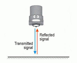
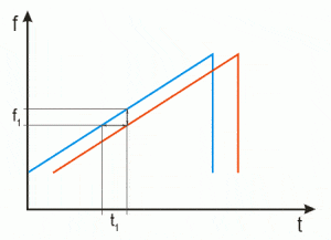
The frequency difference f1 between the transmitted signal and the reflected signal (Fig.2) is proportional to the time of electromagnetic-wave propagation t1 to the product and back. Knowing that the wave velocity is equal to the speed of light and knowing the propagation time, it is easy to calculate the antenna-to-product (reflector) distance.
But this is an ideal case possible only if we have a perfect reflector. In reality, the tank can contain foreign structures, the product surface can be wavy or irregular (loose product), etc. In this case, a pattern of the reflected signal can appear quite different (Fig. 3).
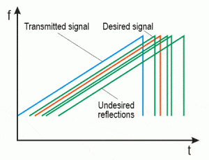
In this case, we cannot determine the frequency difference by simple subtraction. A more complex operation of emitted and received signal mixing is therefore used. This gives us a low-frequency resultant “signal” containing both desired and undesired frequencies rather than a numeric value.
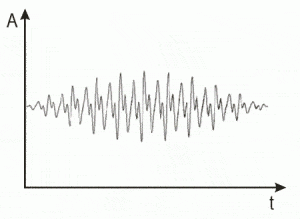
A microprocessor system of the level probe performs further signal processing to determine a frequency of the desired signal and convert its value to the tank filling level value.
To do so, the resultant signal obtained by mixing of the transmitted and received signals undergoes spectral analysis. Using digital processing methods, the frequency signal is converted to a spectral pattern (Fig.5).
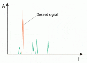
Thereafter, the frequency f of the desired signal is precisely determined and converted to the value of distance from the level-probe antenna to the product surface. To obtain the filling level value, the range value is substracted from the level probe’s installed height entered in the level transmitter.
Solids
- Coal Bunker
- Fly Ash Silo
- Cement Silo
- Clinker Silo
- Iron Ore Bins
- Pellet Silos
- Sinter Silos
- RMHS Silos
- Coke Silo
- PP/ PTA/ LDPE Silos
- Pain Silo
- Urea Silos
- Phosphate Silos
- Dust Bins
- Grain (All kinds of Grains) Silos
- Ground Bunkers
- Bulk Chemical Storage Silos
- Other Silos storing Bulk Solids and Powders
Liquids
- Acids
- Alkalies
- Fuel Oils
- Water
- Slurry
- Steam Applications
- MOLTEN METAL
- Liqor
- Milk
- LIQUIDS with Agitators, Fumes and Vapours
- Other Liquid and Slurry Applications
- ULM 31A1-HF
- ULM 11A1-HF
- ULM 11-HF
Note – Refer Individual Catalogues
Preferred Applications: Solids, Liquids and Slurries
Measuring Range: 50-80 meters
Process Temperatures: -60°to +1600°C
Process Pressure: -0.2 – 40 bar
Signal Output: 2 Wire/ 4-wire with 4 – 20 mA/HART/ RS 485/ Bluetooth (varies for different models)
Emitting Frequency: 120-140 GHz GHz
Supply Voltage: 20 to 32 VDC/ 100- 260VAC (through SMPS)
Power Consumption: Max 1.5 W @ 24 VDC
Hazardous Locations: Explosion Proof Certification
Preferred Applications: Powders and solids
Measuring Range: 50 meters
Process Temperatures: -40°to +185°C
Process Pressure: -0.2 – 40 bar
Signal Output: 4-wire 4 – 20 mA/HART/RS-485/Modbus
Number of Beams: 5
Emitting Frequency: 140 GHz (each beam)
Supply Voltage: 20 to 32 VDC (110/ 230 VAC through SMPS)
Power Consumption: Max 8 W @ 24 VDC
- ULM 31A1-HF – Click here to download the catalogue
- ULM 11A1-HF – Click here to download the catalogue
- ULM 11-HF – Click here to download the catalogue
